Dimensioning and planning of sewers
of sewers
Professional sewer planning is particularly important for successful sewer construction. In the construction of wastewater drainage systems, the requirements of durability, performance capacity and economic viability must be fulfilled in equal measure. On the one hand, attention should be directed at ensuring that the greatest potentials for low construction and operating costs in the planning phase can be achieved, while at the same time the process for the choice of the materials to be used is based on criteria that enable an objective comparison.
Decisive factors for the achievement of the set targets are the planning, the execution of the construction activities, and the components themselves. A comparison of various solution approaches or materials can never be made solely on the basis of price.
Instead, the following preconditions must be fulfilled:
- Equality of performance
- Scope of performance – the performance to be rendered must be known and reproducibly described
- Assessment criteria – the services must contain assessable criteria
To achieve this, the following steps have to be performed:
- Technical assessment
- Economic assessment
- Manufacturing costs
- Operating costs
The results of such a technical-economic comparison are to be summarised as assessment criteria. These assessment criteria must then be specifically weighted for the project in question; the results are determined by adding the assessment figures and are subsequently presented in a general assessment matrix.

Sewer Construction | Planning and Consulting
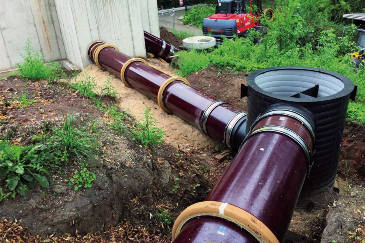
Industrially manufactured vitrified clay pipes and fittings have stood the test of time in this respect since the introduction of municipal and industrial sewer networks. They are optimally suited for the drainage of surface water, combined water and sewage, both as mixed and separate system types. Their properties remain unchanged throughout the entire service life of drains and sewers – under the precondition that they are planned, installed, operated and maintained in compliance with the requirements of the relevant standards, e.g. EN 1610, EN 752, and EN 12056-1.
HYDRAULIC DESIGN OF DRAINS AND SEWERS
 The design of drains and sewers is hydraulically calculated on the basis of the equations of Colebrook-White (a.k.a. the Prandtl-Colebrook equation) and of Manning-Stricker. In these equations, the values of the wall roughness in the hydraulic planning of vitrified clay pipes and drains are not factored in.
The hydraulic design according to these equations, on the other hand, do factor the wall roughness under operating conditions, which is determined primarily by the individual losses over the entire run of the drains and sewers, and also by the deposits and biological sludge that accumulates during the service life of the drainage system. The decisive factor for the value of operating wall roughness is the number and the configuration of chambers within the section of the drainage system being calculated.
Vitrified clay pipes and fittings can be used both for standard installation not only in flat sections, but also in gradient sections with a flow velocity of up to 15 m/s. Due to the very smooth inner face of the pipes, flow velocities of <0.5 m/s are possible. Independent of this, the hydraulic performance must be estimated or designed according to the specific effluent medium.
STRUCTURAL DESIGN OF DRAINS AND SEWERS (STATIC CALCULATION)
 According to the conventional methods for the structural design of drains and sewers, which are described in EN 1295-1, vitrified clay pipes and fittings are classified as rigid pipe systems. On account of their high load-bearing capacity, they are capable of directly absorbing soil and traffic-related loads.
Throughout the entire service life of drains and sewers, there are no load-related pipe deformations or changes to the pipe diameters as a result of either external or internal load effects.
Static calculations are based on the load-bearing capacity (crushing strength) under consideration of soil and traffic loads, as well as other load effects.
The stability of vitrified clay pipes and fittings undergoes no change whatsoever over the entire service life of the system. They are equally resistant to alternating stress loads from road and rail traffic. Their load-bearing capacity is demonstrated by setting the stresses exerted on the pipes in relation to the resistances of the pipes themselves. The safety tolerances that must be borne in mind are described in the respective design regulations.
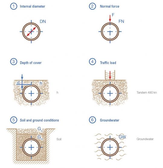
The parameters shown in the following diagram must be considered when dimensioning the vitrified clay pipes:
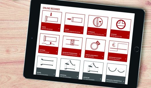
PLANNING TOOLS FOR SEWER CONSTRUCTION
 At Steinzeug-Keramo we attach particular value to supporting planners. A series of time-tested and future-oriented tools and information are available, including personal and individual support services. The website www.steinzeug-keramo.com is the gateway to the world of vitrified clay products, providing information on the essential services and persons of contact for technical and commercial topics:
Structural calculations for vitrified clay pipes in the open trench and trenchless construction methods: with online, prompt and 24/7 availability.
- Hydraulic calculation of circular cross-sections
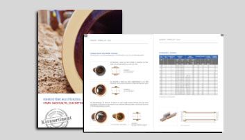
- Tender specifications for vitrified clay products
- Digital documents
- Individual economic-viability calculations
- Planning support for microtunnelling, fr om planning to the selection of the installation method, up to support in the construction phase
- Individual support for open trench installation
During the planning phase of wastewater drainage systems in underground constructions, the following aspects must also be considered:
Jacking forces
The jacking force of the pipe is calculated from the compressive strength and the smallest annular area subjected to the jacking forces. The pressure transmission area is determined by the thickness of the wall at the end of the pipe and the type of pressure transfer ring, and is calculated according to EN 295-7.
Longitudinal compressive strength / maximal operating jacking load
The maximal longitudinal crushing strength must be determined by reducing the jacking strength Fj within the process of the structural calculations, taking the factors of safety into consideration.